

There was a game called Labyrinth Ljubljana, and part of its technical solution was a Control Unit which controlled our custom made flashlights over RF link with cheap chinese module with nRF24L01+ onboard. We need to cover (one way: Control Unit -> Flashlights) an entire Labyrinth house (a stall actually), about 500 m2 in two floors with old-fashioned thick concrete walls. As you can imagine, a small module with external antena did not reliably cover all space, in fact, it barely covered few meters around transmitter. Also, the receiver was inside a flashlight which was held by a player, and human body is mostly out of water which block signal quite efectively.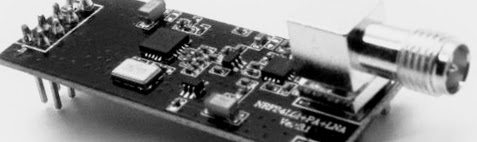
So, we decided to move transmitter to more convenient place, extending SPI bus cable to the same nRF24L01+ module and add a basic Wi-Fi amplifier. From Control Unit room to transmitter room was about 13 meters. There are multiple ways how to achieve this:
- most obvious: connect UTP cable, lower baud rate and see if it works.
- an advanced solution: design a differential driver to transform single-ended signals to differential signals.
Second (advanced) option is most likely to work on longer distances and can be used for faster baudrates, but it introduces additional costs, PCB space and work. If you really need to extend SPI, and other long-range communication standards are not OK (RS-232/422, CAN, LIN, Modbus, Ethernet), this should be an entry point – transforming signals to differential.
In our case this wasn’t an option at all since we needed a solution really fast and couldn’t afford loosing another day (or month). So, what we did was basically a first option with a few hacks:
- Wiring
SPI bus typically has 4 lines: SCK, MISO, MOSI, CS. Aditional nRF24 signals are Chip Enable (RX/TX mode) and IRQ line. Add ground and power supply and you end up with 8 lines which exactly fits standard UTP cable, so we used a cheap chinese CAT5 UTP cable. Inside UTP cable there are 4 twisted pairs and since our data lines are single-ended, it is wise to separate data lines as much as possible and twist them with a stable line (GND, VCC, CE, IRQ) to minimalise crosstalk and interference:
Wire UTP cable with mixed SPI data lines and power supply lines
Additionally, use shielded UTP cable (F/UTP or SF/UTP) to minimise external interference from (as an example) 230V mains power line for LED lightning.
- Power lines
Having a stable power supply rails is a must in every electronic device, even a simple DIY project. Bad grounding or unfiltered power supply line can cause all sort of problems, so you must make sure that nRF24 (or other devices at the other end of this long UTP cable) has a proper power supply. In our case aditional ground line (2 mm2 wire) was routed alongside UTP cable, since it was needed for other stuff at the same location. Anyway, a large smoothing electrolytic (100 uF) and small ceramic (1x 100 nF, 1x 10 nF) capacitor was added directly to power pins or nRF24 module. If other electronic is powered from the same power line, think of using a proper PI-filter for power supply lines. - Transmitter and receiver specifications + line termination
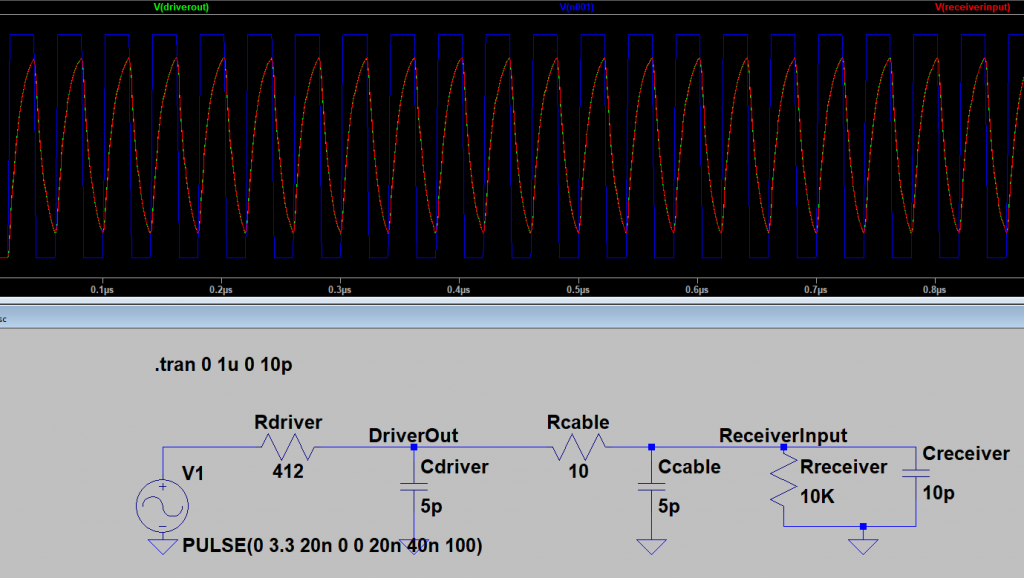
Every device has its IO capabilities and limitations. In our case, we interfaced STM32L1 with nRF24L01+. Usually this specs can be found in device datasheet. STM32L1: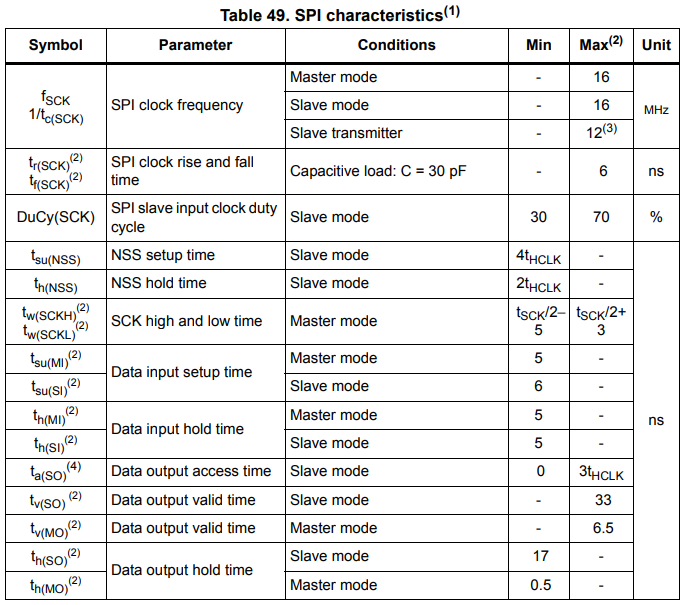 This are hardware driver limitations, and are the best results you can expect at IC pin. Adding external hardware and connections usually only make it worst due additional parasitic capacitance, inductivity and resistance. Both cable and receiver (nRF24L01+) driver must be taken into account. This is a complex subject and can’t be explained in a few lines, but basically we must do whatever it takes to make sure the signal at both end of the cable is appropriate for driver input/output stage and that data transmitted is not corrupted. Mostly this is a problem with bad line termination which causes reflections, overshots and signal degradation due parasitic resistances. Here is made-up example of a line, just to see what could happen to clock signal:
 The most obvious thing is to lower the bus frequency (baud-rate). In our case, only a small amount of control data was transmitting over SPI, so we used really low baud-rate, around 62.5 Kbps. It turned out that we don’t really need any special line termination, but this is just a coincidence. Maybe few meters more/less of UTP cable wouldn’t work, so this is a thing to do a research if signal is altered on the line. There are many articles about line termination out there.
 - nRF24L01+ specifics – shielding
It turned out, that this modules, specially cheap chinese ones, are very prone to external noise, bad power supply and bad grounding. See this and this. I have made (using our Cene the CNC) a small PCB with screw-terminal connector to easily wire UTP cable wires, but if I would have to do it again, I would probably use normal ethernet connector. I prepared a huge GND pads on this PCB and than kitchen-foiled (a layer of random isolator and than aluminium foil) whole connector-nRF24 pack just up to the antena connector. We used nRF24L01+ PA/LNA module.

Without a doubt, there are other hacks to somehow extend SPI cable length. This is only one of them and I don’t claim it is the best, but it worked out well in Labyrinth Ljubljana. This are the most important things to remember, if you decide to follow our path:
- Use shielded UTP (F/UTP or SF/UTP) cable
- Try not to mix signal lines in the same twisted pair.
- Properly filter power supply lines.
- Lower baud-rate as much as you can.
- If needed, include a proper line termination.
- nRF24: shield, power supply, …