Everybody said: “why don’t you just buy a new radio with bluetooth?”. And you can be sure when I say, that I considered this option several times, in fact, almost every day when something didn’t work. But, projects just wouldn’t be fun if everything would work out of the box.
This is going to be a long post, since I will try to fill in the gaps of missing info that I just didn’t find on the web, or was confusing.
For those who are here just to see if it can be done: YES. I have an operating VW RNS MFD2 with bluetooth connection to my phone. For this I sacrifice exernal 6-disc CD changer. Now I have a basic set of playback controls, which also works with steering wheel buttons, and since BT module supports calls, I can also have handsfree calls.
The Idea
The most obvious solution to add BT support to car stereo with AUX is simply by buying a cheap BT module, plug it in and voila. But I want steering wheel controls, handsfree calling and I don’t like power cables and 12V plugs.
NOTE: I already had relatively cheap CD changer emulator with USB and AUX, but it didn’t work well and it had no BT. OK for 25€, but BT is BT after all.
Basic info
- Radio is VW RNS MFD2 (DVD version)
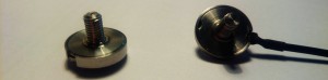
- Previously installed external CD changer: 6-disc VW 1DINCDC (Sony)
NOTE: not VAG CD changer! - New Bluetooth CD Changer emulator (CDCEmulator):
- main CPU: STM32L100-Discovery board
- cheap chinese Bluetooth module: KCX_BT002
- cheap chinese step down converter (12V -> 5V)
- a couple of BC547, BC557, few resistors and electrolytic capacitors (voltage converters and power controls)
- Capabilities:
- Receive all radio commands (PLAY/MUTE, NEXT/PREV, FFW/FBW, CD selection, Scan MIX). CDCEmulator +BT acts as CD 1, some radio commands are silently ignored or re-maped to my wish.
- Other optional but usefull stuff:
- logic analyzer (8€ on ebay)
- USB <-> UART adapter
- osciloscope
- Software:
CDCEmulator Data IN, Data OUT
This is what all of this project is about. Here I spent most of my time trying to figure out what data to send, so radio thought CD changer is present and therefore enable audio input.
CDC Emulator Data IN
This is a communication from radio to CDCEmulator. It sends only a few commands in a respond to user button press or init/deinit request.
- There are many ways to interpret data, so the best way is to just chose one and stick with it. In my case, I found a lot of help on other sites (see below), but at the end still chose to trace communication between CD changer. I’ve also written a PulseView data parser, so it was much easier to figure out what is going on.
- Data is transfere over a single line (no CLK) with 0-5V logic levels.
- Each radio action (user button press, controls) is sent in two packets. The first one is a command, and the last one is like ACK or whatever – always the same.
- Each packet is a four byte message, where only one (third) byte is an actual command. Message start with start sequence (longer high and low pulses) and ‘1’ and ‘0’ is pulse-length-encoded.
- CDCEmulator must send ACK on every command.
- Timings can be seen on the pictures. They might vary for a quite a lot, a couple of hundred microseconds.
- I’ve had a lot of problem with spikes and therefore false interrupts on this line. At the end I’ve software-debounce every pin change.
[BMo_scrollLightboxGallery id=18 slG_vertical=0]
CDCEmulator Data OUT
This is a communication CDCEmulator -> radio. Once CDCEmulator is initialized, it periodically sends 8 byte packets with playback data, deck info, CDCEmulator state and data IN ACK response packets. Sounds simple, but it was quite a challenge to generate the right data. This is also where I was most confused when I read stuff that people already figured out for VAG CD changer.
- Communication protocol is a simple uni-directional SPI, where:
- CDCEmulator is MASTER, radio is SLAVE.
- CLK frequency is apparently not critical. Mine is aroudn 60kHz.
- CLK: polarity = low, phase = 1. Data is interpretted as MSB first.
- You must ensure 0-5V logic levels. In my case, STM32L1 runs on 3V3, and radio was not able to read data before I added 3V3 -> 5V voltage level converter for both lines (CLK, MOSI). Since speed is really low, I didn’t have any problems with line termination or parasitic capacitance.
NOTE: cheap chinese, BIDIRECTIONAL level converters didn’t work for me. Seems like STM32L1 output driver and radio input stage were impedance-mismatched and that caused all kinds of undefined voltage levels.
- CDCEmulator periodically sends packets from the very beginning (on radio power on) until radio sends request to stop (for example, on de init action when user press FM button and don’t want to listen CD anymore).
NOTE: CDCEmulator must stop sending data on radio request, otherwise radio does not power it down gracefully and starts sending repeated de-init requests until timeout. - Each packet consists of 8 bytes. I still don’t know what all bytes mean, although I have record all possible CD changer states – seems like they are somehow related to each other, depends on CD changer state and playback state. However, as it works, you can see the code for more details.
- <mode><CDNum><TrackNum><timeMsb><timeLsb><frame 1-3>
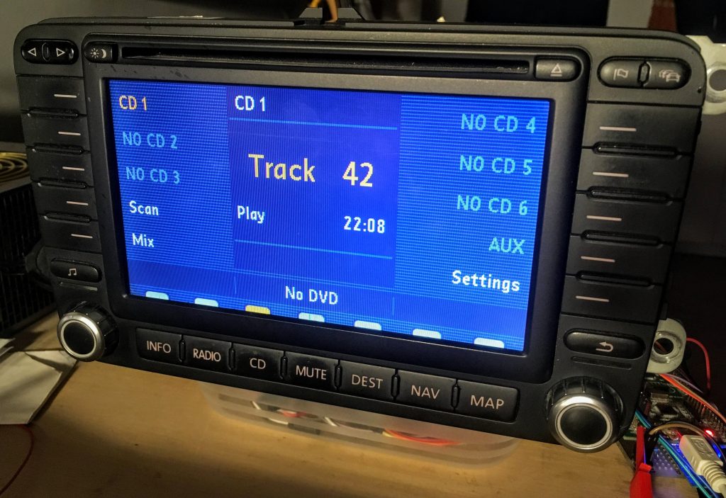
- On power on and init request, CD changer sends CD deck info. That way radio can display available CDs and limit track selection. However, even if radio didn’t receive have deck info, it enables audio output if CDCEmulator mode and state data is correct.
- Radio can’t display track names and it also doesn’t care about what is displaying as long as values are valid. So, I decided to always show CD 1, track 42 (of course) and my birthday on time min/hour fields. Like a boss. 😀
- Timing between packets is also not very critial.
[BMo_scrollLightboxGallery id=19 slG_vertical=0]
Implementation
I am too lazy to write a detailed guide and how-to. I tried to comment more complex parts of the code. Here is some general info, but feel free to ask anything in the comments.
- I used my VS Code STM32 IDE for development. I generate basic peripheral initialization code with CubeMX and I used LL library. I had a lot of problems – I discovered a bug in LL libs and in general I think things could be a lot better, but it still OK, so go for it, unless you plan to write everything from scratch up.
- To read data IN, generate SPI messages, control BT module and be able to print messages over UART, there must not be any blocking code. So here is what I did:
- I created two stopwatch timers with us precision. Good enough since time-limitations are quite loose.
- I created two ring buffers for:
- received data commands
- MOSI data mode/state
- I read data IN line in external interrupt mode with rising and falling detection. Inside interrupt routine I’ve only updated state machine and once whole message was received, I added it the buffer.
Data in handler in main loop checked if buffer is empty and generate response messages or other actions, like control of BT module.
- I generate MOSI messages with timinigs inside MOSI handler, which constantly check time and generate exact byte of a packet at exact time. Things are not trivial here, and can’t think of any good exaplanation why CD changer/radio don’t use more straight-forward approach. At least all bytes within the same packet could be sent at the same time. doh.
- Actions (BT controls) are created as a pulses that simulate BT module button press. Additionally, user can press (for example) radio NEXT button several times, faster than BT module is configured to acknowledge button press. In that case, actions are counted and posponed.
- RNS MFD2 have some its own logic about how&when enable/disable audio input, I assume because of possible unwanted noise on audio line during power up/down or other actions. This is especially a problem with NEXT/PREV command, where radio mute state can be longer than the action is executed (over BT, not old CD changer), and you might not hear song starts. Additionally, NEXT/PREV command mute state is a lot longer if toggled by rotary encoder than buttons on the top-left side)!
- Since user can manipulate BT audio source (phone) manually, you can easily get yourself into a state, where phone is in PLAY mode, while radio is in MUTE state and vice versa. That is why I decided to silently ignore PLAY/MUTE commands, and implement PLAY/MUTE action on FFW command (which is not supported by BT module anyway). That way I can also easily control BT calls and radio mute state. Anyway, this is mine BT-module specific implementation, feel free to change it.
- Pinout is best seen from CubeMX project file. I don’t have any schematic. Except transistor voltage level converters, everything is very simple, directly connected to pins on dev board. Some things you see on PCB are redundant and BT module specific.
[BMo_scrollLightboxGallery id=20 slG_vertical=0]
You can find the code and some more data in our GitHub. Feel free to ask if anything is unclear (unfortunatelly, not everything is as straight forward as I would wish). And good luck with your RNS MFD2 Bluetooth renovation! 🙂
| Get code and example on Damogran Labs GitHub! |