This is the third part of the classy_blocks tutorial. If you’re new to this, you might want to start with part 1.
Most real-life geometry cannot possibly be described using just a single block, regardless of how sophistically you create it. That’s why blockMesh is a block-structured mesh generator, meaning you may specify many blocks (inside each the mesh is technically structured). Often, similar geometries are blocked (sliced into hexahedrons) in a similar fashion so let’s talk about that first.
We’ll focus on round things because they are the most painful to make with blockMesh and therefore most completely represented in classy_blocks (but more non-round shapes will come in the future).
O-grid et. al.
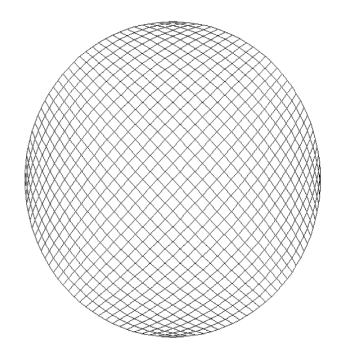
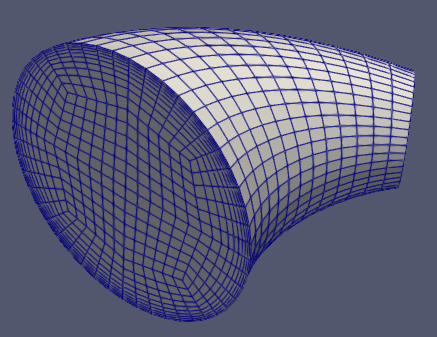
You could take a square Face and made all its edges curved so that it would look like a circle, then extrude it to obtain a cylinder. This would still produce a hexahedral mesh, but parts of it would be really bad with respect to non-orthogonality:
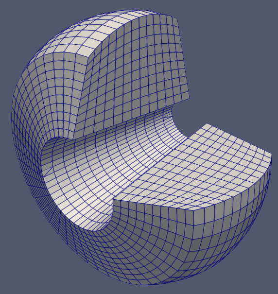
You could slice it like pizza but this will create wedges in the center. They will be tiny compared to other cells and will also have high aspect ratio.

To avoid both of the above we usually divide a circle into multiple blocks – but very carefully so as not to spoil their quality.
H-grid
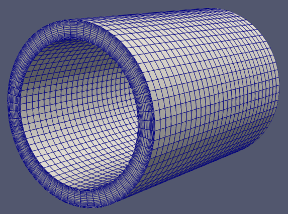
This is approximately the best way one can create a cylindrical shape with hexahedral blocks, see if you can tell how it’s divided:
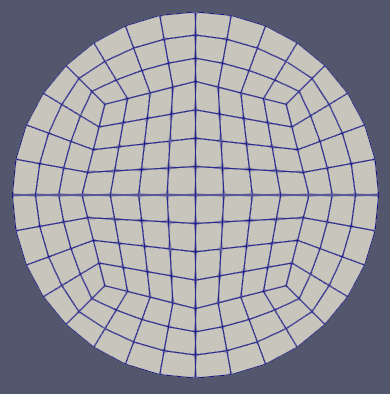
It takes 12 blocks and that’s a lot to specify manually each time. Since cylinders and similar round shapes occur very often in real life (like, piping and stuff), classy_blocks provides a small (but growing) library of predefined Shapes that you can use without studying H- and O-grids and all the stuff.
Cylinder
axis_point_1 = [0, 0, 0]
axis_point_2 = [1, 0, 0]
radius_point_1 = [0, 1, 0]

pipe = cb.Cylinder(axis_point_1, axis_point_2, radius_point_1)
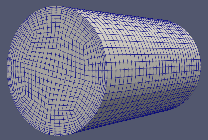
Mind that two points and a radius is sufficient to define a cylinder as a geometric entity but here you need three points. That’s because classy cylinder is divided into blocks and it does matter where how and where they are placed.
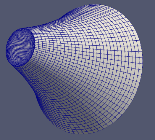
Frustum
Just like a cylinder, it requires a radius point. However, for the other side, a scalar radius is enough.
axis_point_1 = [0, 0, 0]
axis_point_2 = [2, 2, 0]
radius_point_1 = [0, 0, 2]
radius_2 = 1
frustum = cb.Frustum(axis_point_1, axis_point_2, radius_point_1, radius_2)
You can also provide a third – middle – radius. classy_blocks will create a frustum with curved edges that can serve as rounded sections where radius changes. See the venturi tube example.
Short frustums with a large difference in radii have a common problem: they create sharp edges and therefore highly non-orthogonal cells. Currently this is rather difficult to fix with given set of tools. But future optimization capabilities will solve this very simply and quickly – by moving inner points along frustum axis.
Elbow
This Shape got its name after piping elements as it represents them almost exactly. You can specify different start and end radii and what angle it sweeps through.
It’s specification is somewhat verbose but a versatile shape like this requires a large number of parameters…
center_point_1 = [0, 0, 0]
radius_point_1 = [1, 0, 0]
normal_1 = [0, 1, 0]

sweep_angle = -np.pi / 3
arc_center = [2, 0, 0]
rotation_axis = [0, 0, 1]

radius_2 = 0.4

elbow = cb.Elbow(center_point_1, radius_point_1, normal_1, sweep_angle, arc_center, rotation_axis, radius_2)
Rings
ExtrudedRing
This one is much easier to block but just as common and important as cylinders. It has an additional inner_radius parameter. It will create 8 blocks – the same number of outer blocks in a cylinder but you can override that in case you’re doing something weird.
pipe_wall = cb.ExtrudedRing([0, 0, 0], [2, 0, 0], [0, 1, 0], 0.8)
RevolvedRing
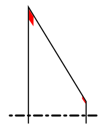
Sometimes you want to specify a ring’s cross-section instead of its start-end-radius-radius. Then RevolvedRing comes to play. With it, you provide an arbitrary Face that provides the ring’s cross-section (given it’s properly oriented) and RevolvedRing will create specified number of Revolve operations to form a ring.
xs_points = [
    [0.1, 0.2, 0],
    [0.8, 0.1, 0],
    [0.7, 0.5, 0],
    [0.2, 0.5, 0],
]
xs_edges = [None, None, cb.Arc([0.3, 0.55, 0]), None]

face = cb.Face(xs_points, xs_edges)

donut = cb.RevolvedRing([0, 0, 0], [1, 0, 0], face)
A properly oriented Face looks like this:

This face will be revolved following the right-hand rule, out of the screen, around the axis of revolution represented with double arrow.
Geometric Accuracy
Although classy_blocks provide means of block creation similar to CAD software, it is not CAD software. It calculates points and edges that blockMesh can devour but surfaces that it generates are some sort of differential equation voodoo we’re not going into. The consequence of this is that (for instance) a revolved shape in CAD will have the same meridional cross-section everywhere but blockMesh will distort it at larger revolve angles. Same applies for other operations and shapes. This is particularly notable for Elbows and Frustums with curved sides.
You can remedy this to some extend by chopping the geometry into smaller blocks. For example, instead of having a single 90-degree elbow, create three 30-degree ones. The smaller the distance between curved edges on a block are, the more accurate they will represent your geometry.
There’s another solution: projecting problematic block faces to more precisely specified surfaces. This is a whole new kind of science and we’ll cover that in a different tutorial.
Chaining
As I stated at the beginning, a single block won’t be enough for a slightly more advanced geometry. Shapes help but even a single Shape isn’t very useful. If you wanted to simulate what’s going on in a 90-degree pipe bend, you’ll need at least 3 Shapes, two Cylinders and an Elbow in between. Specifying all required parameters for each one gets repetitive and annoying, especially because most of them are already calculated by previous shapes. classy_blocks allows you to chain new Shapes to existing ones and only provide missing parameters:
bend = cb.Elbow(...params...)
pipe = Cylinder.chain(bend, pipe_length)
Note that you don’t chain an existing shape instance to a new one – instead, you specify the class of the new shape and a new instance is returned.
Expand/Contract/Fill
Many round geometries feature sudden changes in radius. You need additional blocks to do this but effectively it’s just something like putting a Ring over a Cylinder. Again, you can simply add a Ring where it is supposed to be but there’s a shortcut similar to chaining.
ExtrudedRing.expand(source_round_shape, new_radius)
You can expand a Cylinder as well as an ExtrudedRing to create two concentric rings. Conversely, you can take an ExtrudedRing and create a new concentric one on the inside:
ExtrudedRing.contract(source_extruded_ring, new_radius)
Obviously, you can’t take a ring and put a cylinder over it, therefore there’s no contract() method on a Cylinder. If you have an ExtrudedRing and want to fill it completely, a cylinder should be placed inside. You do this with
Cylinder.fill(source_extruded_ring)
Notice that you can only use ExtrudedRing for those operations, not the revolved one. The irregular shape that revolved rings can have make those methods unreliable and confusing to use.
Counts, Grading and Patches
Chopping
We’ve got our blocks placed but now we have to set cell counts and grading. In classy_blocks lingo, this is called chopping as it quite graphically represents both.
If you recall the first part of the classy_blocks tutorial there’s a chop() method for an Operation but Shapes are better than that. Any round shape has planar start and end surfaces and a curved outer surface. Axial direction goes from start to end, radial from axis to outer and tangential direction goes around the circumference of the shape.
So instead of specifying axis numbers you use much friendlier methods:
cylinder.chop_axial(count=100)
cylinder.chop_radial(end_size=bl_thickness, c2c_expansion=1/1.2)
cylinder.chop_tangential(start_size=cell_size)
Count and grading specification is the same as for operations: use a combination of parameters that suits you most and let classy_blocks calculate the rest.
Patches
Similarly to chopping, patches are set more intuitively:
cylinder.set_start_patch("inlet")
cylinder.set_end_patch("outlet")
cylinder.set_outer_patch("pipe_wall")
Additionally, rings also have a set_inner_patch() method because they have an inner patch, obviously.
A Serious classy_blocks tutorial Example
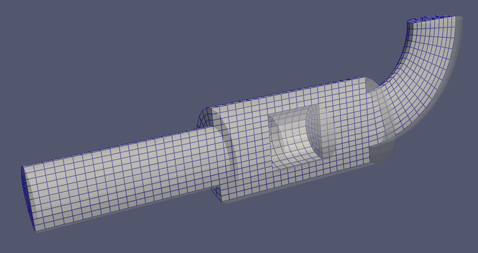
Now let’s utilize most of what we talked about to make a mesh of some sort of a fake muffler. It should resemble something like this:
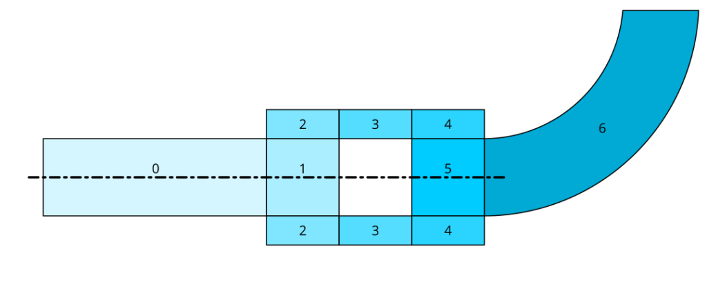
Each shape gets its own number in the sketch. The centerline denotes cylinders and rings, number 6 is an elbow. Behold the script:
#!/usr/bin/env python
import numpy as np
import classy_blocks as cb

# geometry parameters
pipe_radius = 0.05
muffler_radius = 0.08
ref_length = 0.1

# let's make cell size constant for the sake
# of this example
cell_size = 0.015

# shapes: it's often handy to put them in a container;
# indexes in this list are the same as in the sketch
shapes = []

# 0
shapes.append(cb.Cylinder([0, 0, 0], [3 * ref_length, 0, 0], [0, pipe_radius, 0]))
shapes[-1].chop_axial(start_size=cell_size)
shapes[-1].chop_radial(start_size=cell_size)
shapes[-1].chop_tangential(start_size=cell_size)
shapes[-1].set_start_patch("inlet")

# 1
shapes.append(cb.Cylinder.chain(shapes[-1], ref_length))
shapes[-1].chop_axial(start_size=cell_size)

# 2
shapes.append(cb.ExtrudedRing.expand(shapes[-1], muffler_radius - pipe_radius))
shapes[-1].chop_radial(start_size=cell_size)

# 3
shapes.append(cb.ExtrudedRing.chain(shapes[-1], ref_length))
shapes[-1].chop_axial(start_size=cell_size)

# 4
shapes.append(cb.ExtrudedRing.chain(shapes[-1], ref_length))
shapes[-1].chop_axial(start_size=cell_size)

# 5
shapes.append(cb.Cylinder.fill(shapes[-1]))
shapes[-1].chop_radial(start_size=cell_size)

# 6
elbow_center = shapes[-1].sketch_2.center + np.array([0, 2 * muffler_radius, 0])
shapes.append(
    cb.Elbow.chain(shapes[-1], np.pi / 2, elbow_center, [0, 0, 1], pipe_radius)
)
shapes[-1].chop_axial(start_size=cell_size)
shapes[-1].set_end_patch("outlet")

# add everything to mesh
mesh = cb.Mesh()
for shape in shapes:
    mesh.add(shape)

mesh.set_default_patch("walls", "wall")

mesh.write("case/system/blockMeshDict", "debug.vtk")
This example is a bit simplified:
- Most geometry is described using the
ref_lengthparameter. If you wanted to do parametric studies, you’d probably want to specify more crucial parameters separately. - Cell count is kept low so as not to wait for blockMesh to finish while constructing our mesh. You can simply change
cell_sizeto change coarseness. - Inlet and outlet should be made much longer for the flow to steady after (often wrong) inlet/outlet boundary conditions.
- There are no boundary layers. For a proper mesh, you should replace
start_size=cell_sizewith something likestart_size=bl_thickness, c2c_expansion=1.2or something similar. But this is out of scope of this Shapes tutorial.
That’s it for now! Be back soon as tutorials are on the way!