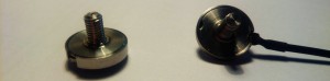
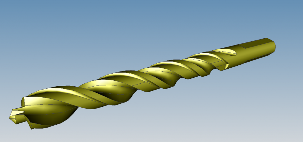
Speaking of involute gears and metric screws, this is another little project that celebrates engineering knowledge. While laying sick in bed I decided to make a 3d model of a drill bit. So I took the largest and the most complicated one from our workshop and modelled it in FreeCAD.
One of the purposes of this little project is to point out a few details about drill bits. How they are often called spiral in our but are helical actually. And how the cross-section increases from tip to shank although the outer diameter stays the same. And that the actual sharpened drilling head isn’t cone-shaped but a little more complicated…
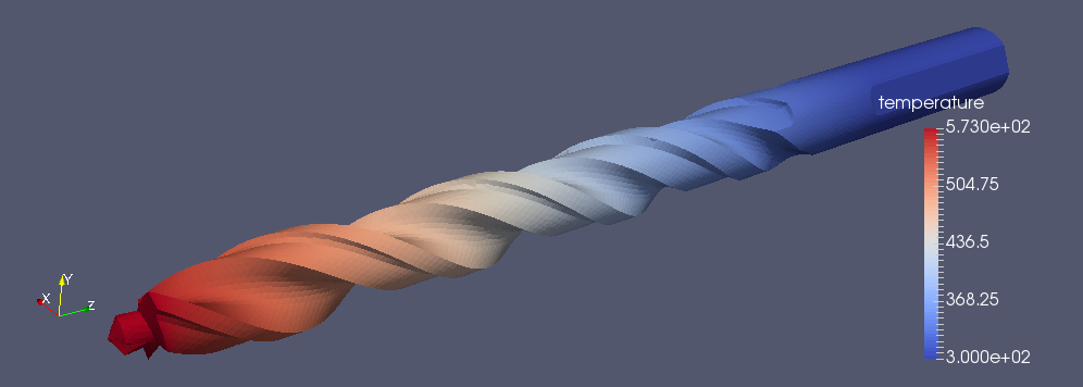
Another purpose is to show off some of FreeCAD abilities. It’s open-source, completely free and quite capable: parametric sketching, basic and advanced 3D operations, drawings, even FEM simulations. Assembly workbench is on the way and so is CAM. I admit, it’s still in very early phase. In my exact case I had to wrestle somewhat with stuff that’s not totally parametric. If I had to change the design I would have to remake some of the steps. But again, since modelling can be scripted in Python I could as well write a script that would produce gazillions of models with a single keypress.
Another purpose of this little project is just to be cool. Like using the model and do a stress or heat transfer analysis or 3D print it or whatever.
The main purpose is, like many our projects, not very well known to us.
Here’s the FreeCAD file for you. Be careful as you might cut yourself on sharp edges. Follow the modelling procedure carefully as it does get a little twisted from step to step. I believe in the future FreeCAD will get a hole lot of new features, making modelling more than a bit easier.
I hope that wasn’t too boring for you, though.