I am not going to share my negative opinion on visual aspects of design of this vehicle (although I could be very verbose) but there are some technical issues I need to clarify. There are statements in style of “Tesla Cybertruck could be insanely aerodynamic” or “Tesla’s Cybertruck Aerodynamics Do Flow Smoothly” or even nonsense such as “Cybertruck could achieve laminar air flow” but there are no numbers to be seen.
Being in a posession of a premium OpenFOAM licence I decided to test these and share the actual numbers. I already did some quick aerodynamic research on trucks so I thought this would be a quick’n’easy run. Of course it wasn’t as it took me a week to wrestle everything together.
Setup
I found a 3D model of Tesla Cybertruck on GrabCAD without even having to search for it as it was the most popular at the moment. To simplify I sealed gaps and removed tyre treads and rounds but left the details on rims.
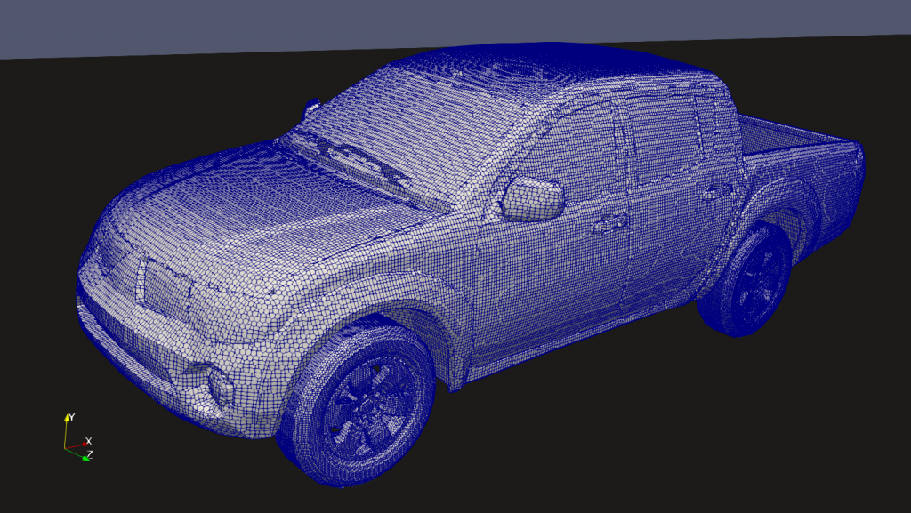
I made two versions, one with open Vault (bed) and one with closed. To measure how insanely good the aerodynamics really are, I picked a random 3D model of an actual pickup and also calculated drag for that. The random pickup was Mitsubishi Triton (L200). Among its specifications is also a figure on drag coefficient so it would also serve me for an approximate validation case.
Technical Details

I created a fluid domain around the models 40m long, 20m wide and 10m high. Final meshes had from 3.5 – 4 million elements. Sensitivity study showed that mesh with approximately 1.5 million cells is already fine enough. The air speed is 90 km/h or 25m/s or 55 mph with density 1.19 kg/m3. I used incompressible steady-state simpleFoam solver with k-Omega SST turbulence modelling. Near-wall flow is modeled with wall functions that switch from laminar to turbulent automatically. To model wheel rotation I added 4 MRF zones with rotating velocities matching air speed. The road is also a moving wall.
To calculate drag coefficient I used forceCoeffs and set reference length to wheelbase length. I included the ’empty’ area between road and underbody in frontal area calculations as it is customary for cars. The velocities in z- and y-directions (perpendicular to driving, x-direction) never reached convergence criteria. That is normal as it implies an instability caused by vortex shedding behind the truck.
Results
Tesla Cybertruck: Closed Vault

Unfortunately I lost the post from another CFD study that showed Cd = 0.46. My study showed Cd = 0.47. Mitsubishi Triton states a figure of 0.46 in specs and my chewed up VW Polo from 2001 has Cd = 0.32.
Neither 0.47 nor 0.46 nor even 0.32 is very impressive. Actually 0.32 is not very hard to achieve as I highly doubt there was a lot of research done on a slow city cart like Polo.
Tesla Cybertruck: Open Vault
To be a bit more fair, I thought I should also compare Cybertruck with other open trucks which, if their beds were closed, would be more aerodynamic by default.
According to my simulation, opening the vault increases drag coefficient from 0.47 to 0.51. An interesting thing is that in all simulations drag coefficient steadied in the first few iterations and then oscillated very little around its average (less than +/-0.01). In this case, it oscillated by more than +/-0.03 so I had to average the results to get a more reliable value. This means there will probably be a rather unpleasant vortex in the open vault or behind the truck at higher speeds.
Mitsubishi Triton

Cd for the L200 is 0.46 from manufacturer’s specifications. I got a value of 0.43 from my simulation, which is a bit suspiciously close match given all the simplifications I had to make on model and simulation.
What’s missing is the front grille (it’s closed with a smooth flat surface) and underbody with relatively little details (only differentials and control arms). There’s also no gaps between doors, cab and bed. The tires are smooth. Boundary layer is modeled with wall functions and mesh is rather coarse for everything that’s happening external flows such as this.
Anyway, models, meshes and simulations are similar enough to be compared and validation shows good match with reality so let’s not get too deep into that.
Difficulties
I had quite some difficulties. Every solution I took could potentially slightly alter the outcome.
- The 3D model of Tesla Cybertruck is not very accurate as not all dimensions match the official specs. I scaled the model to match the specified length. Drag coefficient is calculated using drag force and frontal area, the latter I measured from the model itself. Slightly different width/height ratios get mostly compensated by re-calculated frontal area.
- The models currently available don’t include any of the underbody features (struts, control arms and the general shape). In any case what’s missing are cavities besides wheels and control arms.
- As written before, number of details one can consider in a simulation is limited. Adding gaps and other features would also slightly change the results.
- Getting a free and accurate 3D model of any car is surprisingly hard to get. Either it’s not accurate enough (low-poly) or has too many details which would take too much time to remove. I trusted the models I found on GrabCAD and TurboSquid; I can only assume they are accurate enough for CFD needs.
- Creating a perfect mesh for such turbulent external is almost impossible because of wide range of velocities. Using wall functions requires y+ between 30 and 300 which is impossible in regions with low flow (behind flat surfaces). On the the other side, using resolved mesh with y+ less than 1 would require too many cells where velocity is high. Using automatic wall treatment helps in regions with y+ < 5 and in regions where 30 < y+ < 300, other regions are resolved less accurately. According to my experience in turbomachinery, force calculations are fairly accurate even in invalid regions. This isn’t the case with heat flux calculations but this is not the case here.
- There are some troublesome spots where tyres touch the road. For simulation this means excess pressure and velocities. In real life, that also means excess pressure and velocities. Think of a small puddle of water lifting the whole vehicle during aquaplaning). Fortunately these areas are very small compared to the whole domain. A handful of cells among 4 million) so their impact on results is small.
Colorful Figures for Directors
Here are the results in pictures. Keep in mind any colorful picture could be interpreted in many opposing ways so the numbers are only to be trusted.
See image descriptions in the gallery.
Conclusion
Making a Cheese Louise Mk. 2 and saying it’s the best ever in aerodynamics is a rather wild statment, isn’t it?
P.S.: Anything could achieve laminar flow with low velocity and vice versa. Anything can make the flow turbulent provided the velocities are high enough. RTFM.


